It increases the a dimension and the forces in the beam are a combination of bending and.
Spreader beam design example.
There are a number of ways you can utilise our modular spreader beams for example.
Below the hook lifting devices such as spreader bars and lifting beams must be designed in accordance with asme bth 1 and are to be manufactured and used in accordance with requirements of asme b30 20 which specifies requirements for marking inspection construction and operation.
Spreader beams are universally applied gear which is widely used in various types of lifting operations onshore and offshore.
Spreader beam design spreheet thenavalarch using a spreader beam for lifting stawi industries lifting beam calculation 514372owg2nj lifting beam design spreader adjule self balancing spreader beam diagram schematic and image.
The typical approach to a spreader bar design looks like this.
Alternatively the combination design previously referred to can be used.
Design 1 typical spreader bar design.
We would like to show you a description here but the site won t allow us.
In this the beam is suspended from a sling connected part way along the beam rather than at the ends.
This example has an i beam down the center and a series of lugs welded on the top for attaching to the crane.
Asme b30 20 bth 1.
Need a span of 20m 66 but are only lifting 70t we can provide you with a mod 250 70 giving you cone adapters and.
As some of you may have guessed in this example the broom is the spreader beam.
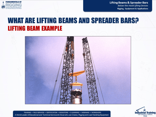
In summary whenever the force must travel along the beam bending stress occurs and that is what we would call a lifting beam.
Custom applications have one of our engineers custom design a spreader beam for virtually any lift.
In this article we will explore the design of a basic spreader beam and see what design checks are needed to establish the suitability of a spreader beam for particular lifting operation.
This spreader beam also has a series of lugs on the bottom to attach to the product.

